The motor transmits power to the drum around which the steel wire rope is wound through a speed redu
Learn More
The multi-rope friction hoist is mainly composed of an electric motor, a reducer, a friction wheel,
Learn More
The JKMD mining hoist is a friction-type (multi-rope) mine hoist used for deep shaft lifting in coal
Learn More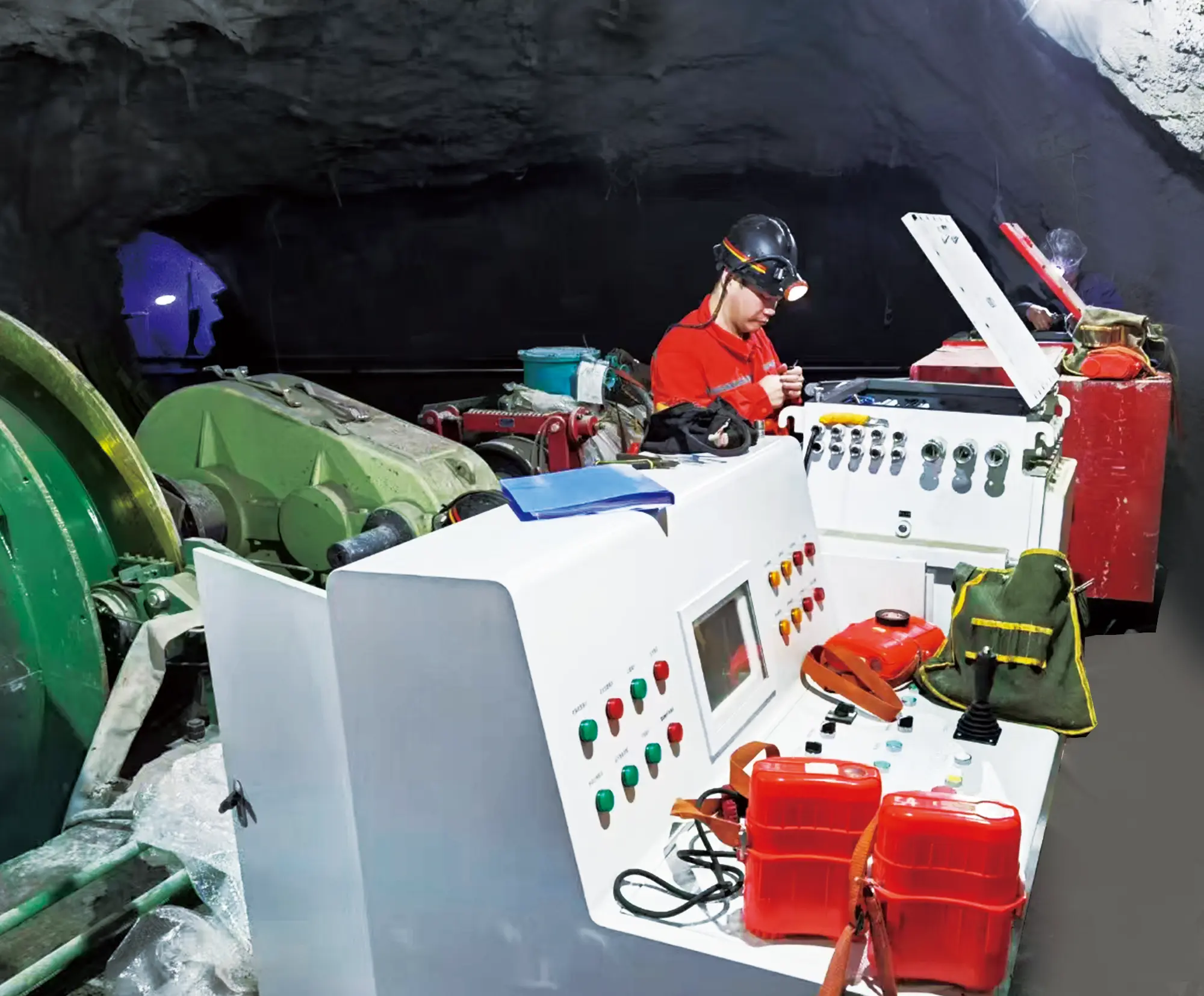
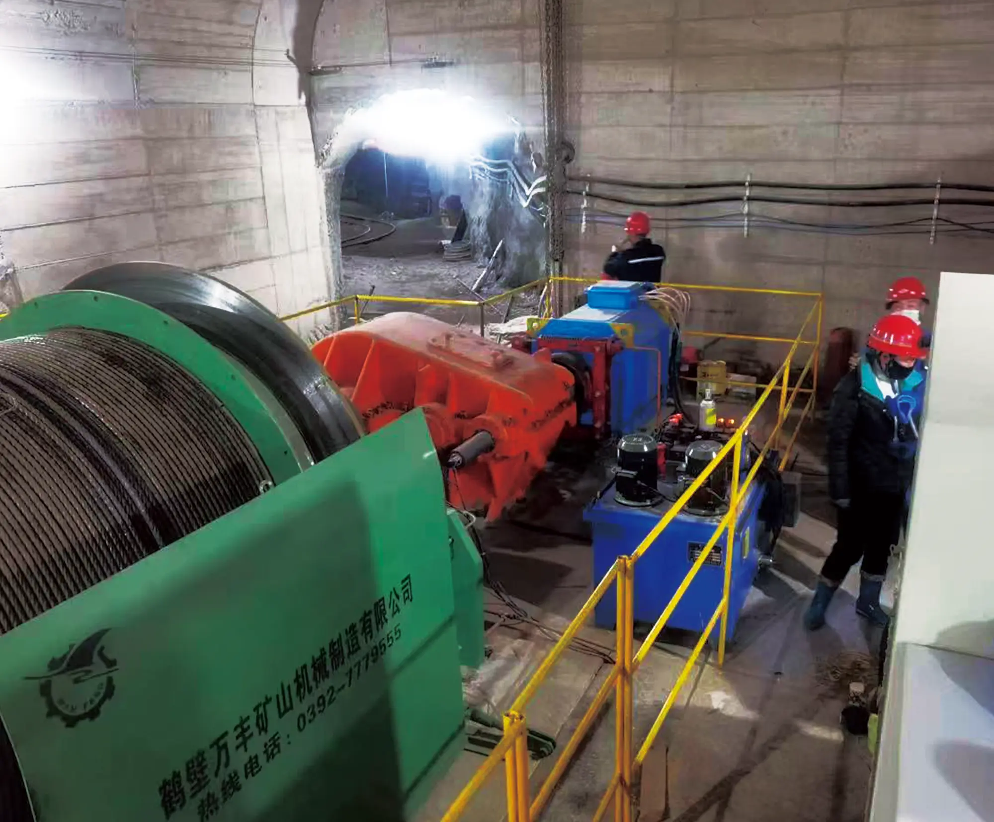
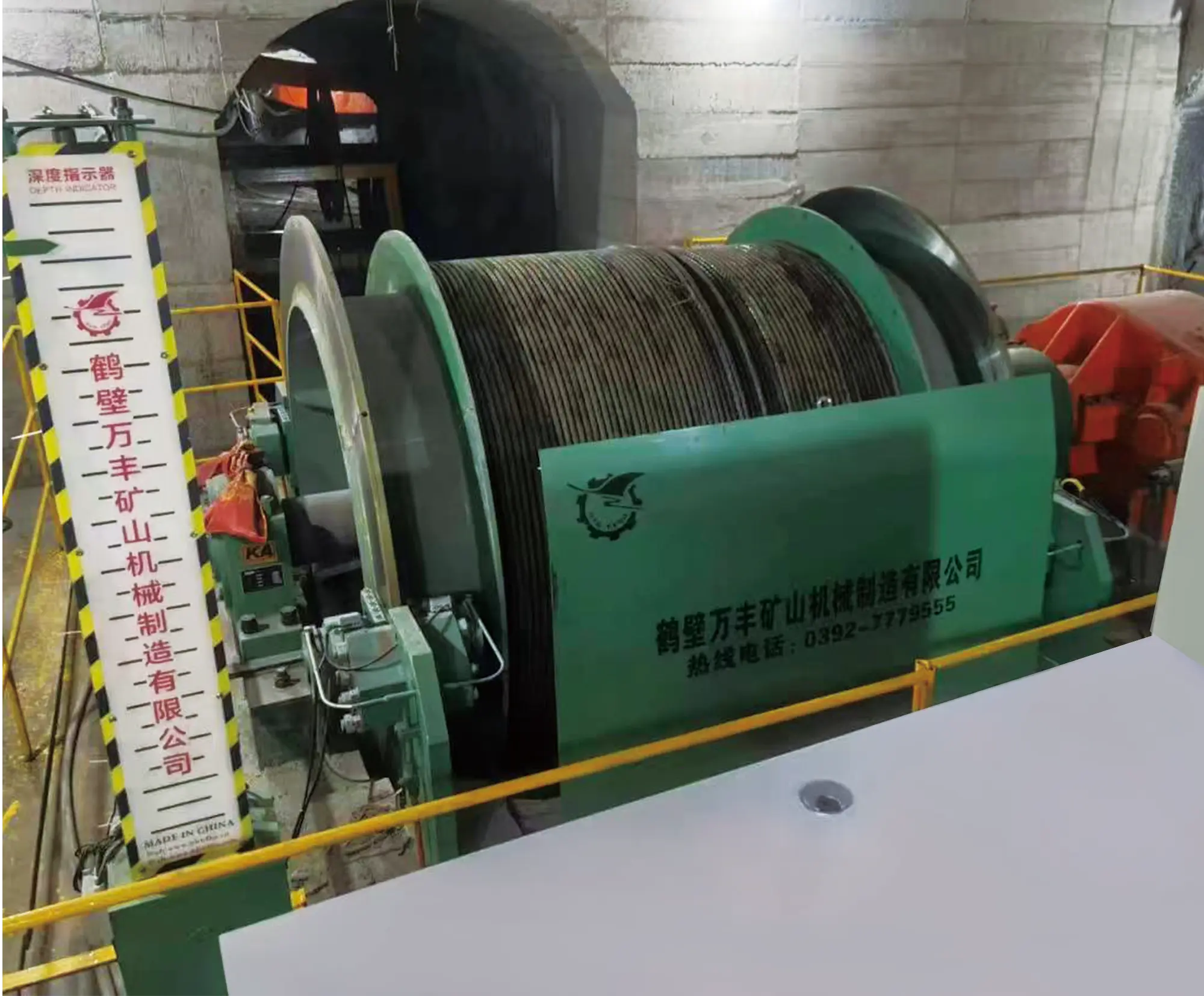
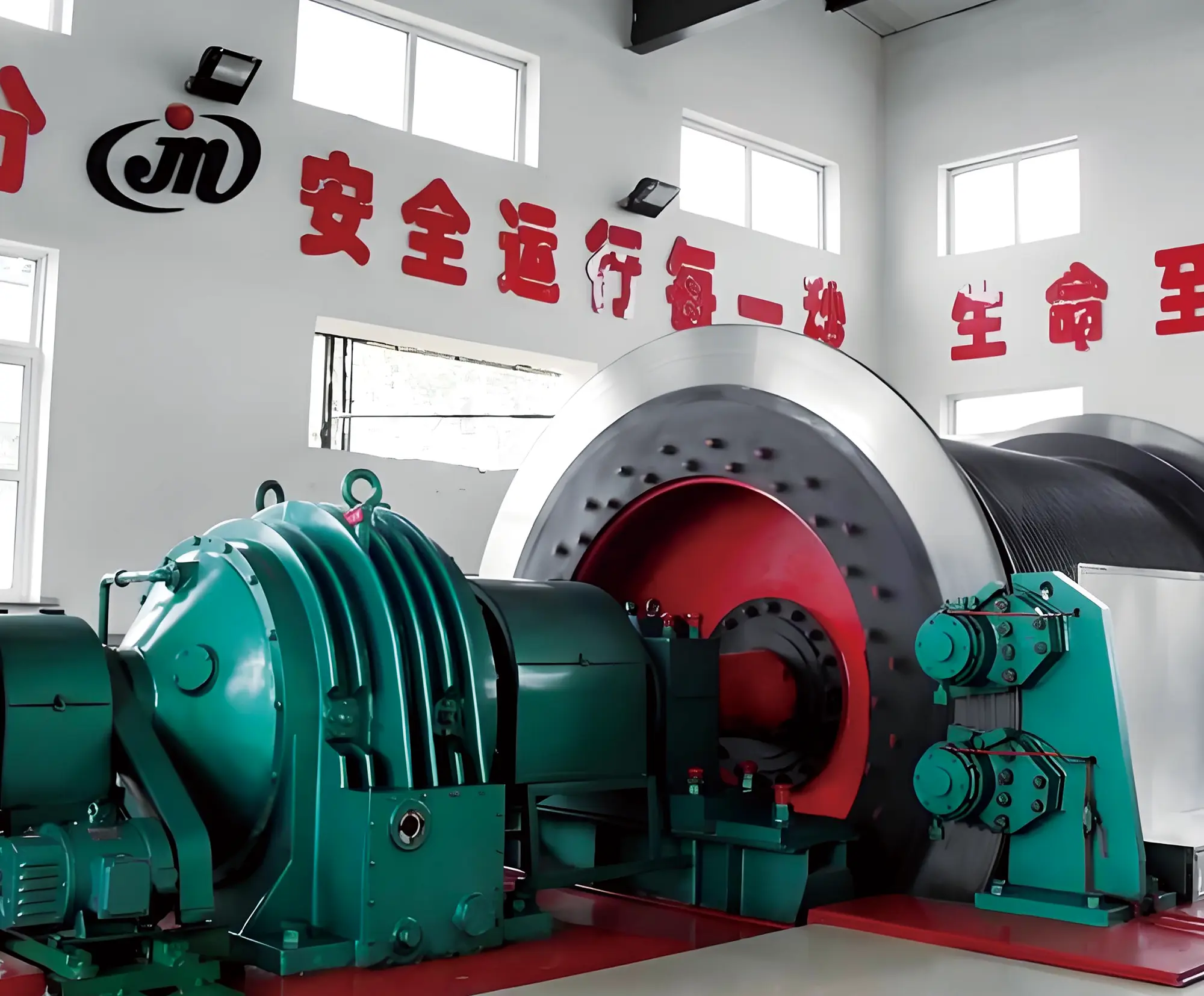
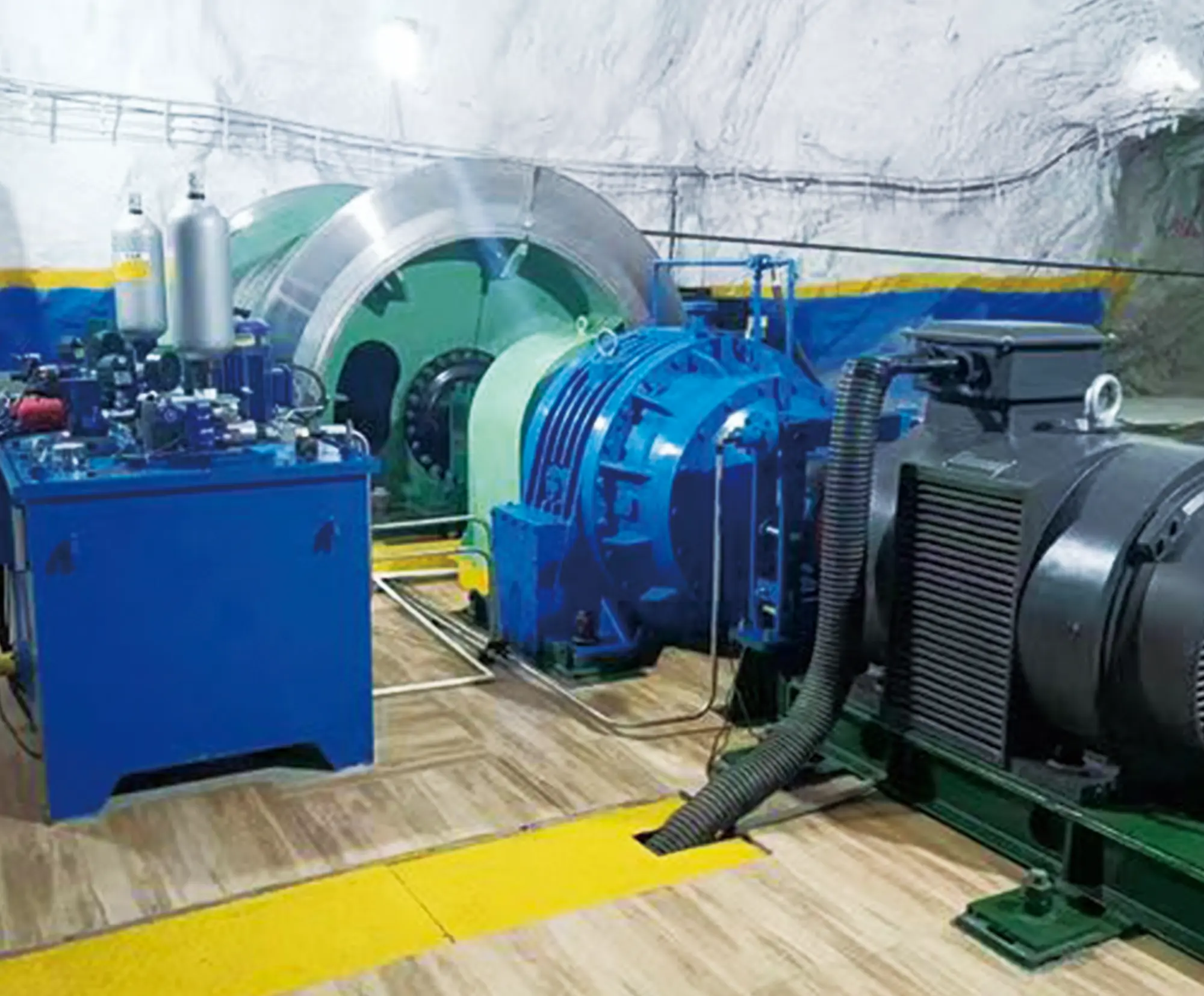
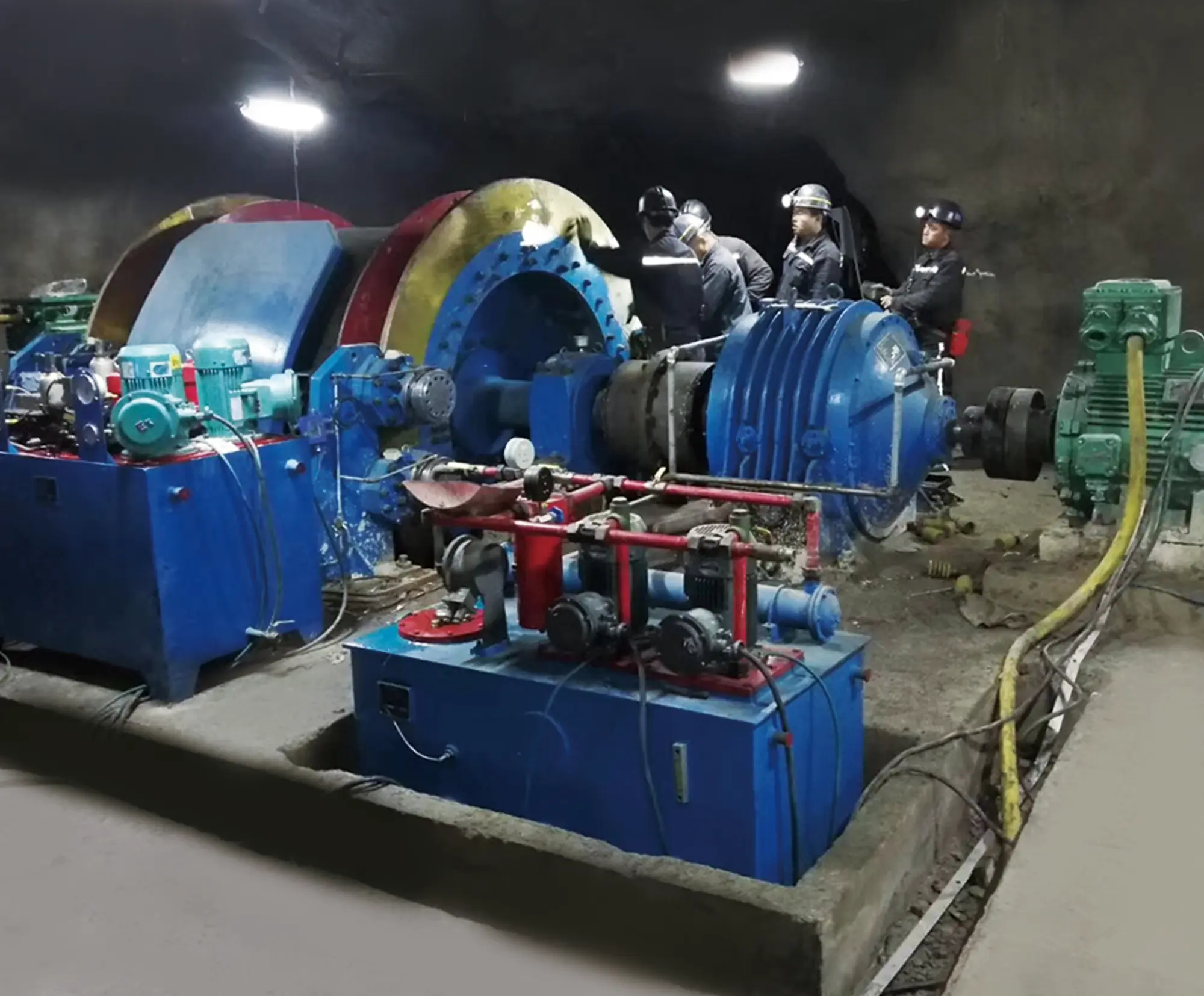
The JK series explosion-proof mining hoisting winch is specially designed for mines containing explosive gases such as gas and coal dust. It is suitable for vertical shafts, inclined shafts or inclined tunnels in coal mines, metal mines and non-metallic mines. It is used for lifting personnel, hoisting coal, ore, gangue, and lowering materials and equipment. It can also be used in other traction and transportation scenarios with explosion-proof requirements.
Working Principle
The motor transmits the power to the reel wound with the wire rope through the reducer to realize the lifting and lowering of the container, The speed is adjusted through electrical control. The disc brake is braked by hydraulic and electrical control. The machine,electricity, and hydraulic joint control system composed of various transmission sensors and control components realize the monitoring and protection of the whole machine, and realize the information transmission inside and outside the hoist through computer and network technology.
| Model | Drum | Maximum Static Tension of Wire Rope | Maximum Static Tension Difference | Wire rope diameter | Minimum Sum of Breaking Forces | Lifting Height or Transport Length | Lifting Speed | Motor Speed | |||||||
| unit | Diameter | Width | Center distance between two drums | manned | Load | manned | Load | 1st layer | 2nd layer | 3rd layer | |||||
| m | kN | mm | kN | m | m/s | r/min | |||||||||
| JKB-2×1.5P | 1 | 2 | 1.5 | - | 62 | 32 | 558 | 295 | 586 | 914 | 5.2 | 1000 | |||
| JKB-2×1.8P | 1.8 | 366 | 730 | 1132 | |||||||||||
| JKB-2.5×2P | 2.5 | 2 | 83 | 40 | 747 | 403 | 802 | 1245 | 5 | 750 | |||||
| JKB-2.5×2.3P | 2.3 | 473 | 944 | 1460 | |||||||||||
| JKB-3.0×2.2P | 3 | 2.2 | 135 | 50 | 1215 | 447 | 887 | 1378 | 6 | ||||||
| JKB-3.0×2.5P | 2.5 | 518 | 1030 | 1596 | |||||||||||
| JKB-3.5×2.5P | 3.5 | 2.5 | 180 | 57 | 1689 | 386 | 809 | - | 7 | ||||||
| JKB-3.5×2.8P | 2.8 | 442 | 922 | - | |||||||||||
| 2JKB-2×1P | 2 | 2 | 1 | 1.09 | 62 | 40 | 32 | 558 | 177 | 346 | 550 | 7 | |||
| 2JKB-2×1.25P | 1.25 | 1.34 | 236 | 467 | 733 | ||||||||||
| 2JKB-2.5×1.2P | 2.5 | 1.2 | 1.29 | 83 | 65 | 40 | 747 | 215 | 422 | 670 | 8.8 | ||||
| 2JKB-2.5×1.5P | 1.5 | 1.59 | 286 | 564 | 885 | ||||||||||
| 2JKB-3.0×1.5P | 3 | 1.5 | 1.59 | 135 | 90 | 50 | 1215 | 282 | 553 | 873 | 10.5 | ||||
| 2JKB-3.0×1.8P | 1.8 | 1.89 | 353 | 697 | 1090 | ||||||||||
| Note 1: The maximum lifting speed is an estimated value based on the nominal diameter of the drum and single-layer winding. | |||||||||||||||
| Note 2: The maximum lifting speed shall not exceed the values specified in the table and in sections 5.2.13 to 5.2.15 of AQ 1035-2007. | |||||||||||||||
| Note 3: The lifting height or transport length listed in the table is calculated based on the maximum wire rope diameter specified in the table. | |||||||||||||||
| Note 4: The ratio of the drum diameter to the wire rope diameter for above-ground hoists shall not be less than 80; for underground hoists, the ratio shall not be less than 60. | |||||||||||||||